- 您现在的位置:买卖IC网 > Sheet目录307 > ADE7761AARSZ-RL (Analog Devices Inc)IC ENERGY METERING 1PHASE 20SSOP
�� �
�
�ADE7761A�
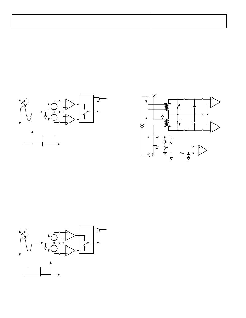
�Fault� with� Active� Input� Greater� than� Inactive� Input�
�If� V� 1A� is� the� active� current� input� (that� is,� being� used� for� billing),�
�and� the� voltage� signal� on� V� 1B� (inactive� input)� falls� below� 93.75%�
�of� V� 1A� ,� the� fault� indicator� becomes� active.� Both� analog� inputs�
�are� filtered� and� averaged� to� prevent� false� triggering� of� this� logic�
�output.� As� a� consequence� of� the� filtering,� there� is� a� time� delay� of�
�approximately� 3� sec� on� the� logic� output� FAULT� after� the� fault�
�event.� The� FAULT� logic� output� is� independent� of� any� activity� on�
�outputs� F1� or� F2.� Figure� 28� shows� one� condition� under� which�
�FAULT� becomes� active.� Because� V� 1A� is� the� active� input� and� it� is�
�still� greater� than� V� 1B� ,� billing� is� maintained� on� V� 1A� ,� that� is,� no�
�swap� to� the� V� 1B� input� occurs.� V� 1A� remains� the� active� input.�
�Calibration� Concerns�
�Typically,� when� a� meter� is� being� calibrated,� the� voltage� and�
�current� circuits� are� separated,� as� shown� in� Figure� 30.� This�
�means� that� current� passes� through� only� the� phase� or� neutral�
�circuit.� Figure� 30� shows� current� being� passed� through� the� phase�
�circuit.� This� is� the� preferred� option� because� the� ADE7761A�
�starts� billing� on� the� input� V� 1A� on� power-up.� The� phase� circuit�
�CT� is� connected� to� V� 1A� in� Figure� 30.� Because� there� is� no� current�
�in� the� neutral� circuit,� the� FAULT� indicator� comes� on� under�
�these� conditions.� However,� this� does� not� affect� the� accuracy� of�
�the� calibration� and� can� be� used� as� a� means� to� test� the� functionality�
�of� the� fault� detection.�
�V� 1A�
�V� 1A�
�FILTER�
�AND�
�FAULT�
�IB�
�CT�
�R� F�
�V� 1A�
�V� 1B�
�A�
�COMPARE�
�0V�
�AGND�
�V� 1A�
�V� 1B�
�V� 1N�
�B�
�TO�
�MULTIPLIER�
�AGND�
�RB�
�V� 1A�
�C� F�
�V� 1N�
�V� 1B� <� 93.75%� OF� V� 1A�
�FAULT�
�<0�
�>0�
�6.25%� OF� ACTIVE� INPUT�
�V� 1B�
�ACTIVE� POINT� –� INACTIVE� INPUT�
�TEST�
�CURRENT�
�IB�
�RA� 1�
�RB� 1�
�VR� 1�
�CT�
�RB�
�C� F�
�0V�
�R� F�
�V� 2P�
�C� F�
�V� 1B�
�Figure� 28.� Fault� Conditions� for� Active� Input� Greater� than� Inactive� Input�
�V�
�R� F�
�C� T�
�V� 2N�
�Fault� with� Inactive� Input� Greater� than� Active� Input�
�Figure� 29� illustrates� another� fault� condition.� If� the� difference�
�between� V� 1B� ,� the� inactive� input,� and� V� 1A� ,� the� active� input� (that�
�is,� being� used� for� billing),� becomes� greater� than� 6.25%� of� V� 1B� ,�
�the� FAULT� indicator� becomes� active� and� a� swap� over� to� the� V� 1B�
�input� occurs.� The� analog� input� V� 1B� becomes� the� active� input.�
�Again,� a� time� constant� of� about� 3� sec� is� associated� with� this�
�swap.� V� 1A� does� not� swap� back� to� the� active� channel� until� V� 1A� is�
�greater� than� V� 1B� and� the� difference� between� V� 1A� and� V� 1B� —in�
�this� order—becomes� greater� than� 6.25%� of� V� 1A� .� However,� the�
�FAULT� indicator� becomes� inactive� as� soon� as� V� 1A� is� within�
�6.25%� of� V� 1B� .� This� threshold� eliminates� potential� chatter�
�between� V� 1A� and� V� 1B� .�
�240V� rms�
�1� RB� +� VR� =� RF.�
�Figure� 30.� Conditions� for� Calibration� of� Channel� B�
�If� the� neutral� circuit� is� chosen� for� the� current� circuit� in� the�
�arrangement� shown� in� Figure� 30,� this� may� have� implications� for�
�the� calibration� accuracy.� The� ADE7761A� powers� up� with� the�
�V� 1A� input� active� as� normal.� However,� because� there� is� no�
�current� in� the� phase� circuit,� the� signal� on� V� 1A� is� zero.� This�
�causes� a� fault� to� be� flagged� and� the� active� input� to� be� swapped�
�to� V� 1B� (neutral).� The� meter� can� be� calibrated� in� this� mode,� but�
�the� phase� and� neutral� CTs� may� differ� slightly.� Because� under�
�no-fault� conditions� all� billing� is� carried� out� using� the� phase� CT,�
�the� meter� should� be� calibrated� using� the� phase� circuit.� Of�
�V� 1A�
�V� 1B�
�V� 1A�
�A�
�FILTER�
�AND�
�COMPARE�
�FAULT�
�course,� both� phase� and� neutral� circuits� can� be� calibrated.�
�MISSING� NEUTRAL� MODE�
�0V�
�AGND�
�V� 1A�
�V� 1B�
�V� 1N�
�B�
�TO�
�MULTIPLIER�
�The� ADE7761A� integrates� a� novel� fault� detection� that� warns�
�and� allows� the� ADE7761A� to� continue� to� bill� in� case� a� meter� is�
�connected� to� only� one� wire� (see� Figure� 31).� For� correct�
�V� 1A� <� 93.75%� OF� V� 1B�
�FAULT� +� SWAP�
�<0�
�V� 1B�
�>0�
�ACTIVE� POINT� –� INACTIVE� INPUT�
�operation� of� the� ADE7761A� in� this� mode,� the� V� DD� pin� of� the�
�ADE7761A� must� be� maintained� within� the� specified� range� (5� V�
�±� 5%).� The� missing� neutral� detection� algorithm� is� designed� to�
�work� over� a� line� frequency� of� 45� Hz� to� 55� Hz.�
�6.25%� OF� INACTIVE� INPUT�
�Figure� 29.� Fault� Conditions� for� Inactive� Input� Greater� than� Active� Input�
�Rev.� 0� |� Page� 18� of� 24�
�发布紧急采购,3分钟左右您将得到回复。
相关PDF资料
ADE7761BARSZ-RL
IC ENERGY METERING 1PHASE 20SSOP
ADE7768ARZ-RL
IC ENERGY METERING 1PHASE 16SOIC
ADE7769ARZ-RL
IC ENERGY METERING 1PHASE 16SOIC
ADM8843ACPZ-REEL7
IC LED DRVR WHITE BCKLGT 16LFCSP
ADP1653ACPZ-R7
IC LED DRVR PHOTO FLASH 16-LFCSP
ADP1712-EVALZ
BOARD EVALUATION ADP1712
ADP1720-EVALZ
BOARD EVAL FOR ADP1720-ADJ
ADP2140CPZ-REDYKIT
REDYKIT 2 BOARDS ADP2140ACPZ
相关代理商/技术参数
ADE7761ARS
制造商:Rochester Electronics LLC 功能描述: 制造商:Analog Devices 功能描述:
ADE7761ARS-REF
制造商:Analog Devices 功能描述:ENERGY METER IC W/FAULT&MNEUT DETEC. - Bulk
ADE7761ARSRL
制造商:AD 制造商全称:Analog Devices 功能描述:Energy Metering IC with On-Chip Fault and Missing Neutral Detection
ADE7761B
制造商:AD 制造商全称:Analog Devices 功能描述:Energy Metering IC with On-Chip Fault and Missing Neutral Detection
ADE7761BARS
制造商:Rochester Electronics LLC 功能描述: 制造商:Analog Devices 功能描述:
ADE7761BARS-REF
制造商:AD 制造商全称:Analog Devices 功能描述:Energy Metering IC with On-Chip Fault and Missing Neutral Detection
ADE7761BARS-RL
制造商:AD 制造商全称:Analog Devices 功能描述:Energy Metering IC with On-Chip Fault and Missing Neutral Detection
ADE7761BARSZ
功能描述:IC ENERGY METERING 1PHASE 20SSOP RoHS:是 类别:集成电路 (IC) >> PMIC - 能量测量 系列:- 产品培训模块:Lead (SnPb) Finish for COTS
Obsolescence Mitigation Program 标准包装:2,500 系列:*